


Hayward ProGrid DE4820 Filter Diagram & Part List
Hayward DE4820 Filter Diagram & Part List with Linked Grids, Tank Parts, Clamp Assemblies, and Air Relief Components
This illustrated DE4820 diagram includes all key filter parts and clickable product links, helping you quickly match internal elements and tank hardware for your system.
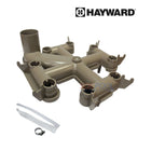
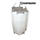
The Hayward Element Cluster DEX4800DC includes all internal DE grids and installs inside the DE4820 as shown in the diagram layout.
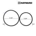
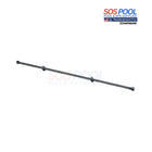
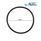
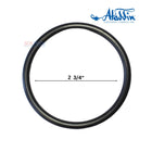
Seal the manifold standpipe securely with the Hayward O-Ring DEX2400Z5, located near the center of the grid cluster as diagrammed in the DE4820 system.
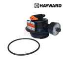
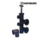
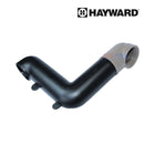
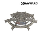
The Hayward Top Manifold DEX2400C sits at the top of the DE grid assembly and directs water across the filter, visible in the top section of the diagram.
Match the original filter layout using the FS-2004 DE Filter Grids, which include seven full and one partial element for the DE4820 configuration.
The Hayward Tank Seal DEX2422Z2 reinforces the seal between the upper and lower halves of the DE4820, as shown between the clamp and tank body.
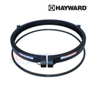
Secure the tank assembly using the Hayward Clamp Kit DEX2421JKIT, which locks the top and bottom sections of the DE4820 tank together per the diagram.
Forming the lower structure of the unit, the Hayward Lower Tank Body DEX2420ATC supports the internal components and is clearly marked in the bottom portion of the filter diagram.
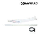
The Hayward Filter Head DEX4820BTC encloses the top of the DE4820 filter and includes the clamp assembly shown at the top of the diagram.
Browse the diagram above to identify exact part locations and click any link here to order replacement DE4820 components with free shipping and best online prices.